Osmium MIMU48XC / MIMU4X6C*

A Massive Inertial Sensor Array Module

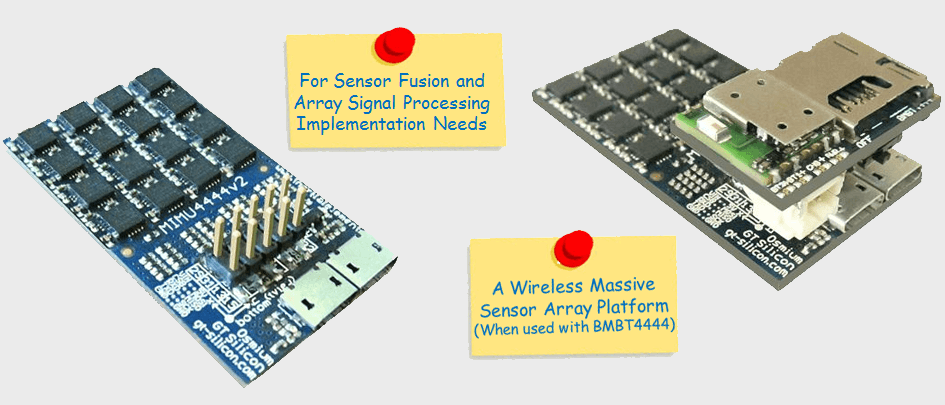
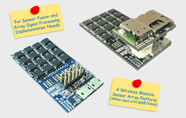
The Osmium MIMU48XC / MIMU4X6C is a variant of massive inertial sensory array module MIMU4844 / MIMU4462, with a 10-pins connector for primarily allowing access to UART and SPI IOs of the micro-controller. In short, MIMU48XC / MIMU4X6C = MIMU4844 / MIMU4462 + 10-pins Connector.

The MIMU48XC / MIMU4X6C, when used with the extension board BMBT4444, is capable of storing data in micro SD card, operating on (re-chargeable Li-ion) battery power and most importantly, wireless communication with the application platform. It operates as a completely standalone module when used with BMBT4444 and a battery.

Product Brief

*The difference between MIMU48XC and MIMU4X6C is the IMU's model number. MIMU48XC includes 9-axis ICM-20948, whereas MIMU4X6C makes use 6-axis MPU-6500. Communication interface of MIMU48XC / MIMU4X6C is compatible with MIMU4X4C. MIMU4X6C is the 6-axis version of MIMU4X9C. MIMU4X4C's support material can be referred for MIMU48XC and MIMU4X9C also.

Highlighting Features

  • A Massive 32 IMUs array: Two 4x4 IMU arrays.
    • MIMU48XC : Array of 9-axis IMUs (Gyro + Accelero + Magneto)
    • MIMU4X6C : Array of 6-axis IMUs (Gyro + Accelero)
  • Data storage in microSD card (with BMBT4444).
  • Option to disable select IMU chipsets for power saving
  • IMUs’ placement and orientation to minimize systematic errors.
  • Parallel communication with IMUs using 32 parallel s/w I2C buses.
  • Sensor fusion and calibration compensation on-board.
  • Floating pt controller AT32UC3C with 512 Kb internal flash.
  • USB 2.0 data interface, All sensors accessible through USB.
  • JTAG programmable (needs dedicated JTAG cable).
  • Power with USB; LED indicators; 49.3mm x 26.6mm.
  • MIMU48XC = MIMU4844 + 10-pins Connector.
  • MIMU4X6C = MIMU4462 + 10-pins Connector.
  • Access to UART and SPI IOs.
  • Access to power ports to enable battery operability.

Supporting Softwares

  • Framework for sensors’ i/f and data comm
  • ZUPT based inertial navigation.
  • Command based data communication protocol.
  • Access to meaningful intermediate variables.
  • Easy to modify, highly modular s/w design.
  • Open source communication scripts for PC.

Multi-IMU Array Platforms

There are typically three categories of multi-sensor systems. First, classical sensors system with different types of collocated sensors, e.g. a positioning system making use of a collocated inertial sensor, a pressure sensor and a GPS. Second, sensor joint systems wherein multiple same type of sensors coordinate to predict state of a system, e.g. estimating motion of a robotic or a human arm using multiple sensors attached to different positions, for capturing a versatile motion. The third kind of multi sensors system consists of collocated sensors with the same properties. The redundancy due to multiple sensors, results not only in enhanced noise performance of the system, but also allows the multi sensor system to achieve what single sensor system can not, e.g. a two dimensional array of accelerometers on a rigid circuit board can produce rotational information. On the one hand enhancing capabilities, shrinking size and reducing cost of MEMS sensors favor redundancy, but on the other hand data communication, processing and calibration compensation pose system level challenges.

Support

Please visit Support section for resources, tutorials, FAQs etc and Blog for more information on technology.

BMBT4444

( An Extension Module to MIMU48XC / MIMU4X9C )

Product Overview

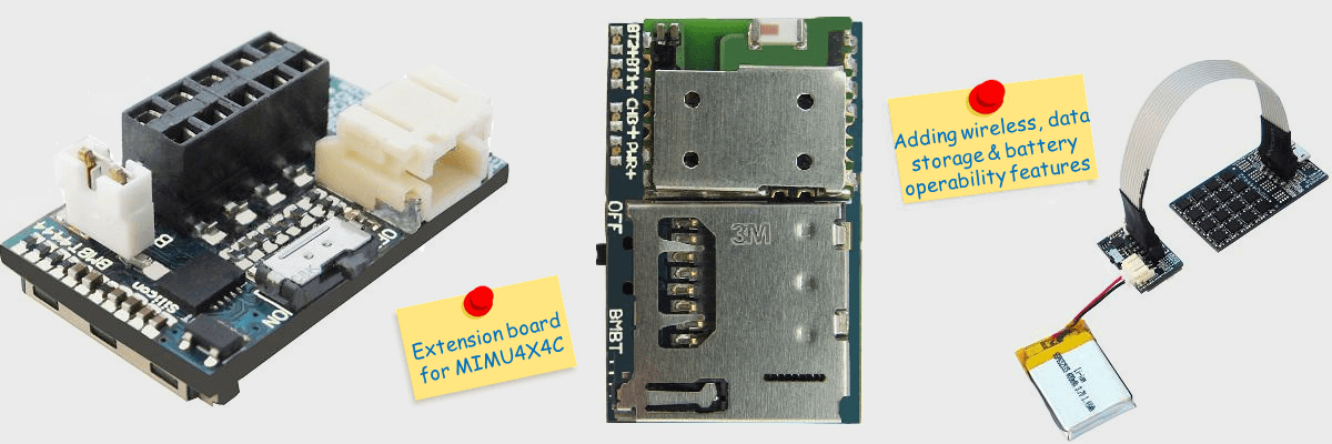
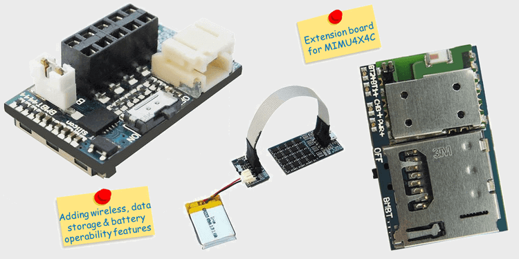
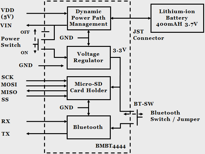
The BMBT4444 serves the purpose of extension board for MIMU48XC / MIMU4X6C. When used with MIMU48XC / MIMU4X6C, it adds wireless communication interface (Bluetooth), data storage (Micro SD Card) and battery (Li-ion rechargeable) as another powering option to the inertial sensor array module.

The BMBT4444 enables the Osmium MIMU48XC / MIMU4X6C to operate as an standalone module.

Highlighting Features

  • Bluetooth version v3.0; Micro SD card holder.
  • Power with Li-ion battery, USB; USB battery charging.
  • Power ON-OFF Switch; LED indicators for power and status.
  • JST battery connector; Option to disconnect Bluetooth.
  • 10-pins female connector (2.54 mm pitch) with UART, SPI and power IOs.
  • Size: 26.6mm x 16.7mm.

Functional Diagram

Support

Please visit Support section for resources, tutorials, FAQs etc and Blog for more information on technology